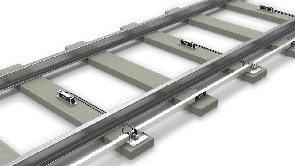

- A non-conventional monitoring system designed by Sisgeo for automatic survey of longitudinal deformation of the rail tracks and the twisting of sleepers.
- Sisgeo RDS Railway Deformation System to monitor the rail track geometry as: longitudinal level: measured in “mm” as a difference of level between two points located longitudinally at certain preset intervals; transversal alignment: measured in “%” as inclination change of two sleepers located at the same intervals of longitudinal.
- Compared to the traditional systems, including topographic surveys, RDS offers to the Customers either high performances and significant reduction of the operating costs.
- In fact when the system is correctly installed there is not field activity required by technicians at site; RDS can be managed also by a single operator on the Web.
| PRODUCT CODE | 0S7RDSHDT02 | 0S7RDSHDL00 |
| Model |
RDS-T: Transverse RDS gauge The RDS -T consists of an aluminum sensor body with a steel anchor plate. It can be installed on concrete or wooden ties (sleepers). It is supplied with two 2 meter cables and waterproof connectors. The RDS-T is suitable for monitoring of railway tracks with temporary support (i.e. Essen method). |
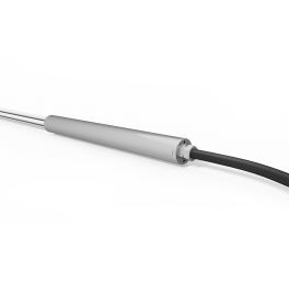
RDS-L: Longitudinal RDS gauge The RDS-L consists of a MEMS tilt sensor mounted inside square-section aluminum tubing. The bar includes telescoping joint at one end, an optical target, and an anchor plate. The anchor plate is suitable for concrete ties (sleepers), and has extra mounting holes to allow for up to 150 mm variations in the distance between ties |
| Measurement principle | uniaxial MEMS digital inclinometer | uniaxial MEMS digital inclinometer |
| Measuring range | ±10° (±5° on request) | ±10° (±5° on request) |
| Sensor repeatability | 0.0013° | 0.0013° |
| Sensor resolution | 0.00056° | 0.00056° |
| Sensor mechanical bandwidth | 18 Hz | 18 Hz |
| Sensor stability @ 30 days (1) | <0.007° | <0.007° |
|
Sensor accuracy: Lin. MPE(2) Pol. MPE(2 |
<± 0.02% FS (±0.020 mm with ±10° range) <± 0.01% FS (±0.010 mm with ±10° range) |
<± 0.02% FS (<±0.070 mm/m with ±10° range) <± 0.01% FS (<±0.035 mm/m with ±10° range) |
| Power supply | from 8 to 28 Vdc | from 8 to 28 Vdc |
| Signal output (3) | RS485, Modbus RTU (5) | RS485, Modbus RTU (5) |
| Sensitivity (4) | see calibration report | see calibration report |
| A/D converter | 32 bit, precision 38-kSPS | 32 bit, precision 38-kSPS |
| Average consumption | 4.3 mA @ 24 Vdc, 8.0 mA @ 12 Vdc | 4.3 mA @ 24 Vdc, 8.0 mA @ 12 Vdc |
| Temperature operating range | -30° to +70°C | -30° to +70°C |
|
Internal temperature sensor: - measuring range - resolution - accuracy |
Embedded on electronic board - 40°C to +125°C 0.01 °C ±1°C with temperature range -10°C to +85°C |
Embedded on electronic board - 40°C to +125°C 0.01 °C ±1°C with temperature range -10°C to +85°C |
| IP class | IP67 | IP67 |
| Connectors | two 5-pin connectors, waterproof up to 1.0 MPa | two 5-pin connectors, waterproof up to 1.0 MPa |
| Sensor cables (included) | two cables, 2 m each (5) | two cables, 2 m each (5) |
| Max cable lenght to logger | refer to F.A.Q.#073 on Sisgeo web site | refer to F.A.Q.#073 on Sisgeo web site |