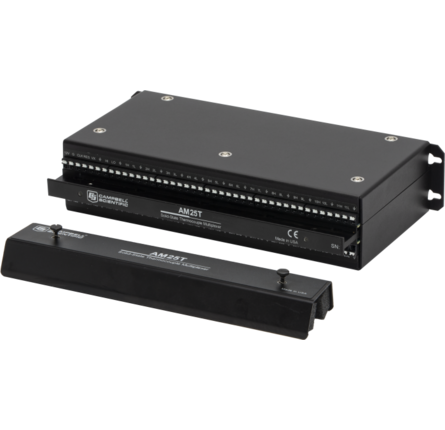
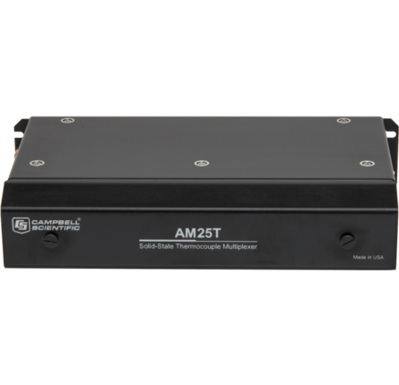
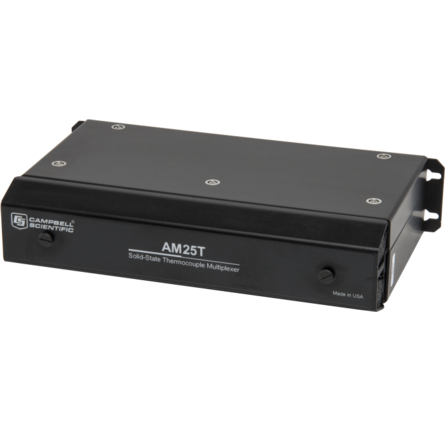

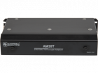


The AM25T 25-Channel Solid State Multiplexer increases the number of thermocouples that you can measure using a Campbell Scientific data logger. The multiplexer interfaces with the data logger and adds terminals so that you can wire additional thermocouples or other low-level voltage output sensors.
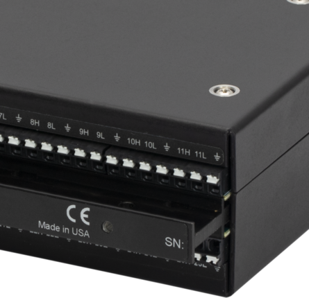
Up to 25 thermocouples are sequentially connected to a common differential channel on the AM25T. (Note: Other low-level voltage output sensors that do not exceed the common mode range of the data logger can also be measured. The AM25T should NOT be used to measure resistive bridges or configured with a voltage divider between the AM25T and the data logger; ask about our AM16/32B multiplexer for these applications.) The output from this channel is wired to a differential input channel on the data logger. As the AM25T sequentially changes channels, the data logger measures the output from each thermocouple in sequence.
A PRT attached to the AM25T’s grounding bar provides a temperature reference for the thermocouple measurements. The heat capacity of the grounding bar and an insulated aluminum cover reduce thermal gradients along the length of the multiplexer. Reducing the thermal gradients allow more accurate measurements.
| Expandability |
|
| Internal PRT Accuracy |
|
| Power | 9.6 to 16 Vdc (under load), unregulated |
| Typical Relay Resistance | 500 Ω |
| Maximum Switching Current | 25 mA (Switching currents greater than 25 mA will damage the relays and render them unusable.) |
| CE Compliance | Conforms to EN55022-1:1995 and EN50082-1:1992. |
| Operating Temperature Range | -40° to +85°C |
| Operating Humidity Range | 0 to 95% (non-condensing) |
Typical Current Drain
| Quiescent | 0.5 mA |
| Active | 1.0 mA |
Enable Levels
| Inactive | < 0.9 V |
| Active | 3.5 to 5 V |
Clock
| Levels | Scan advance occurs on the falling edge of the clock pulse (from above 3.5 V to below 1.5 V) |
| Minimum ON Time | 50 µs |
| Minimum OFF Time | 60 μs |