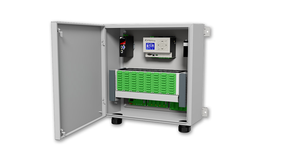
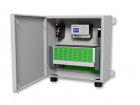
The OMNIAlog has been designed “in house” by Sisgeo and is the result of over 25 years experience using different dataloggers in geotechnical field.
OMNIAlog is a versatile, cost effective and low powered datalogger supporting vibrating wire and all major geotechnical sensors. OMNIAlog has a mini web server on board, 8 or 24 local analog channels, expandable to 408 channels through multiplexers and 2 digital opto-isolated input ports.
It can be managed by any Internet browser and also includes a USB flash drive support.
| CPU AND MEMORY | OMNIALOG GT-816 | OMNIALOG GT-2400 | OMNIALOG GT-100D |
| Processor | ARM Cortex-M3 MCU with 1 MB Flash, 120 MHz CPU, ART Accelerator, Ethernet | ARM Cortex-M3 MCU with 1 MB Flash, 120 MHz CPU, ART Accelerator, Ethernet | ARM Cortex-M3 MCU with 1 MB Flash, 120 MHz CPU, ART Accelerator, Ethernet |
| RAM Memory | 1 Mbyte RAM with backup | 1 Mbyte RAM with backup | 1 Mbyte RAM with backup |
| Mass storage | SD CARD 2 GB (*) for data (about 5Mega data points) and WEB pages | SD CARD 2 GB (*) for data (about 5Mega data points) and WEB pages | SD CARD 2 GB (*) for data (about 5Mega data points) and WEB pages |
| Clock accuracy |
High precision RTC (real time clock with battery back-up) self compensated in temperature (3ppm @ 25°C, 10ppm @ -30 +70°C) |
High precision RTC (real time clock with battery back-up) self compensated in temperature (3ppm @ 25°C, 10ppm @ -30 +70°C) | High precision RTC (real time clock with battery back-up) self compensated in temperature (3ppm @ 25°C, 10ppm @ -30 +70°C) |
| On-board sensors | Temperature measured on the electronic board (accuracy ±1%) | Temperature measured on the electronic board (accuracy ±1%) | Temperature measured on the electronic board (accuracy ±1%) |
| INPUT | |||
| Analog differential inputs | 8 differentials, individually configured. Channel expansion provided by SISGEO multiplexers | 24 differentials individually configured. Channel expansion provided by SISGEO multiplexers | - |
| Digital inputs |
Two opto-isolated digital inputs individually selectable for switch closure, high frequency pulse and trigger. Independent 32-bit counters for each input. Max Input Voltage: 24V (Max Current: 10mA) Min Input Voltage: 5V (Max Current: 2mA) |
Two opto-isolated digital inputs individually selectable for switch closure, high frequency pulse and trigger. Independent 32-bit counters for each input. Max Input Voltage: 24V (Max Current: 10mA) Min Input Voltage: 5V (Max Current: 2mA) |
Two opto-isolated digital inputs individually selectable for switch closure, high frequency pulse and trigger. Independent 32-bit counters for each input. Max Input Voltage: 24V (Max Current: 10mA) Min Input Voltage: 5V (Max Current: 2mA) |
| INTERFACES | |||
| Display & Keyboard | Small backlight graphic LCD 128x64 dpi with membrane keyboard for the minimal local management without the PC. Keyboard for start a uniscan, sequential display of the last memorized readings for each channel (sensor ID, converted unit reading, UM), device status, data download and FW/web pages update by USB pen drive, safe mode (back-up/format/restore internal SD card) | Small backlight graphic LCD 128x64 dpi with membrane keyboard for the minimal local management without the PC. Keyboard for start a uniscan, sequential display of the last memorized readings for each channel (sensor ID, converted unit reading, UM), device status, data download and FW/web pages update by USB pen drive, safe mode (back-up/format/restore internal SD card) | Small backlight graphic LCD 128x64 dpi with membrane keyboard for the minimal local management without the PC. Keyboard for start a uniscan, sequential display of the last memorized readings for each channel (sensor ID, converted unit reading, UM), device status, data download and FW/web pages update by USB pen drive, safe mode (back-up/format/restore internal SD card) |
| LAN ethernet isolated | 10/100 Mbps, RJ45 | 10/100 Mbps, RJ45 | 10/100 Mbps, RJ45 |
| RS232 |
9-pin, DE9: DCE port for GSM/GPRS modem connection Baud Rates: selectable from 9600 bps to 115.2 kbps (default setting) Default Format: 8 data bits; 1 stop bits; no parity |
9-pin, DE9: DCE port for GSM/GPRS modem connection Baud Rates: selectable from 9600 bps to 115.2 kbps (default setting) Default Format: 8 data bits; 1 stop bits; no parity |
9-pin, DE9: DCE port for GSM/GPRS modem connection Baud Rates: selectable from 9600 bps to 115.2 kbps (default setting) Default Format: 8 data bits; 1 stop bits; no parity |
| USB | USB 2.0 flash drive only (FAT 32), 5 V 200 mA | USB 2.0 flash drive only (FAT 32), 5 V 200 mA | USB 2.0 flash drive only (FAT 32), 5 V 200 mA |
| RS485#1 opto-isolated |
5 screw clamp: DCE port for max. No.250 SISGEO digital sensors Communication interface: RS485 Communication protocol: MODBUS RTU (SISGEO Protocol) The voltage ‘V OUT’ is switched on and off under program control. V OUT is the unregulated input power supply ‘V IN’ (1 A) Power supply management (always on or energy safe) |
5 screw clamp: DCE port for max. No.250 SISGEO digital sensors Communication interface: RS485 Communication protocol: MODBUS RTU (SISGEO Protocol) The voltage ‘V OUT’ is switched on and off under program control. V OUT is the unregulated input power supply ‘V IN’ (1 A) Power supply management (always on or energy safe) |
5 screw clamp: DCE port for max. No.250 SISGEO digital sensors Communication interface: RS485 Communication protocol: MODBUS RTU (SISGEO Protocol) The voltage ‘V OUT’ is switched on and off under program control. V OUT is the unregulated input power supply ‘V IN’ (1 A) Power supply management (always on or energy safe) |
| RS485#2 opto-isolated |
5 screw clamp: DCE port for max. 16 SISGEO multiplexer boards connection. Communication interface: RS485 Communication protocol: MODBUS RTU (SISGEO Protocol) The voltage ‘V OUT’ is switched on and off under program control. V OUT is the unregulated input power supply ‘V IN’ (1 A) Every channel of each multiplexer board is completely independent. |
5 screw clamp: DCE port for max. 16 SISGEO multiplexer boards connection. Communication interface: RS485 Communication protocol: MODBUS RTU (SISGEO Protocol) The voltage ‘V OUT’ is switched on and off under program control. V OUT is the unregulated input power supply ‘V IN’ (1 A) Every channel of each multiplexer board is completely independent. |
5 screw clamp: DCE port for max. 16 SISGEO multiplexer boards connection. Communication interface: RS485 Communication protocol: MODBUS RTU (SISGEO Protocol) The voltage ‘V OUT’ is switched on and off under program control. V OUT is the unregulated input power supply ‘V IN’ (1 A) Every channel of each multiplexer board is completely independent. |
| SWITCHED OUTPUT POWER SUPPLY |
The voltage ‘V OUT’ is switched on and off under program control. V OUT is the unregulated input power supply ‘V IN’ (2 A) |
The voltage ‘V OUT’ is switched on and off under program control. V OUT is the unregulated input power supply ‘V IN’ (2 A) |
The voltage ‘V OUT’ is switched on and off under program control. V OUT is the unregulated input power supply ‘V IN’ (2 A) |
| Measurement rate (MR) |
High precision measurement (low speed, 5 sps): Init. analog (with auto-calibration): 27.80 sec Instrument warm-up: depending on sensor configuration Measurement: 5.41 sec Standard measurement (20 sps): Init. analog (with auto-calibration): 7.1 sec Instrument warm-up: depending on sensor configuration Measurement: 1.57 sec Fast measurement (High speed 40 sps): Init. analog (no auto-calibration): 2.65 sec Instrument warm-up: depending on sensor configuration Measurement: 0.45 sec Note1: times indicated not valid for vibrating wire measures Note2: init. analog phase is made only one time before the measurement cycle |
High precision measurement (low speed, 5 sps): Init. analog (with auto-calibration): 27.80 sec Instrument warm-up: depending on sensor configuration Measurement: 5.41 sec Standard measurement (20 sps): Init. analog (with auto-calibration): 7.1 sec Instrument warm-up: depending on sensor configuration Measurement: 1.57 sec Fast measurement (High speed 40 sps): Init. analog (no auto-calibration): 2.65 sec Instrument warm-up: depending on sensor configuration Measurement: 0.45 sec Note1: times indicated not valid for vibrating wire measures Note2: init. analog phase is made only one time before the measurement cycle |
High precision measurement (low speed, 5 sps): Init. analog (with auto-calibration): 27.80 sec Instrument warm-up: depending on sensor configuration Measurement: 5.41 sec Standard measurement (20 sps): Init. analog (with auto-calibration): 7.1 sec Instrument warm-up: depending on sensor configuration Measurement: 1.57 sec Fast measurement (High speed 40 sps): Init. analog (no auto-calibration): 2.65 sec Instrument warm-up: depending on sensor configuration Measurement: 0.45 sec Note1: times indicated not valid for vibrating wire measures Note2: init. analog phase is made only one time before the measurement cycle |
| Type of measurements | mA, mV, V, mV/V, °C, Hz (µsec, digit) | mA, mV, V, mV/V, °C, Hz (µsec, digit) | - |
| ADC |
24-bit (22 true bit) differential Analog-to-Digital Converters, 5SPS, 0-24 Average Function, auto-calibration and auto-range |
24-bit (22 true bit) differential Analog-to-Digital Converters, 5SPS, 0-24 Average Function, auto-calibration and auto-range |
- |
| Range and power supply |
Current loop (2 wires): range 0÷25 mA Power supply (selectable by the software, up to 100 mA): 24V DC, 10V DC, external Transmitter (3-4 wires): range 0÷25mA Power supply (selectable by the software, up to 100 mA): 24V DC, 10V DC, external Voltage (4 wires): range ±10mV, ±100mV, ±1V, ±10V Power supply (selectable by the software, up to 100 mA): 24V DC, 20V DC, 10V DC, 5 V DC ,external Servo inclinometer: range ±5V Power supply (selectable by the software): ±12V DC (dual), external Wheatstone bridge (6 wires, with sensing): range ±10mV/V Power supply (selectable by the software, up to 80 mA): 10 V DC , 5 V DC, external (max 10 Vdc) Maximum bridge resistance: 10 kΩ Minimum bridge resistance: 200 Ω Platinum RTD (Pt100): range -150°C to +150°C Power supply: 1.2 mA Potentiometer: range ±2.5V Power supply (selectable by the software): 10V DC, 5V DC Thermistor (NTC): range -50°C to +150°C Power supply: 0.05mA / 0.1mA / 1.2mA Vibrating Wire: range 400Hz to 6000Hz Excitation sine wave signal (adaptive): ±10 V |
Current loop (2 wires): range 0÷25 mA Power supply (selectable by the software, up to 100 mA): 24V DC, 10V DC, external Transmitter (3-4 wires): range 0÷25mA Power supply (selectable by the software, up to 100 mA): 24V DC, 10V DC, external Voltage (4 wires): range ±10mV, ±100mV, ±1V, ±10V Power supply (selectable by the software, up to 100 mA): 24V DC, 20V DC, 10V DC, 5 V DC ,external Servo inclinometer: range ±5V Power supply (selectable by the software): ±12V DC (dual), external Wheatstone bridge (6 wires, with sensing): range ±10mV/V Power supply (selectable by the software, up to 80 mA): 10 V DC , 5 V DC, external (max 10 Vdc) Maximum bridge resistance: 10 kΩ Minimum bridge resistance: 200 Ω Platinum RTD (Pt100): range -150°C to +150°C Power supply: 1.2 mA Potentiometer: range ±2.5V Power supply (selectable by the software): 10V DC, 5V DC Thermistor (NTC): range -50°C to +150°C Power supply: 0.05mA / 0.1mA / 1.2mA Vibrating Wire: range 400Hz to 6000Hz Excitation sine wave signal (adaptive): ±10 V |
- |
| Reading resolution |
1 µA at range 20 mA - 1 µV at range ±10 mV 10 µV at range ±100 mV - 100 µV at range ±1 V 1 mV at range ±10 V - 0.1 °C for Pt100 - 0.1 °C for NTC 0.1 Hz at range 6000 Hz - 0.001 mV/V at range ±10 mV/V |
1 µA at range 20 mA - 1 µV at range ±10 mV 10 µV at range ±100 mV - 100 µV at range ±1 V 1 mV at range ±10 V - 0.1 °C for Pt100 - 0.1 °C for NTC 0.1 Hz at range 6000 Hz - 0.001 mV/V at range ±10 mV/V |
- |
| Measurement accuracy | 0.01% F.S. (0.1% F.S. for Pt100 and NTC) with Standard Measurement. Calibration in Sisgeo laboratories recommended every 2 years. | 0.01% F.S. (0.1% F.S. for Pt100 and NTC) with Standard Measurement. Calibration in Sisgeo laboratories recommended every 2 years. | - |
| Temperature drift | < 10 ppm / °C, range -30°C to +70°C | < 10 ppm / °C, range -30°C to +70°C | - |
| Input noise voltage | 5,42 µVpp | 5,42 µVpp | - |
| Input limits | ±12V | ±12V | - |
| Sustained input voltage w/o damage | ±50V DC max | ±50V DC max | - |
| DC common mode rejection | >105dB | >105dB | - |
| Normal mode rejection | >90dB | >90dB | - |
| Input impedance | 20 MΩ typical | 20 MΩ typical | - |
| OUTPUT | |||
| Digital output | One relay output (for alarm, etc.): volt-free closure (low voltage 30V, 2A) | One relay output (for alarm, etc.): volt-free closure (low voltage 30V, 2A) | One relay output (for alarm, etc.): volt-free closure (low voltage 30V, 2A) |
| DIGITAL INPUTS | |||
| Measurement rate (MR) | Max frequency 1kHz | Max frequency 1kHz | Max frequency 1kHz |
| Accuracy | 0.1 Hz | 0.1 Hz | 0.1 Hz |
| ENVIROMENTAL CONDITIONS | |||
| Operating temperature | -30 to +70°C (display -20 to +70°C) | -30 to +70°C (display -20 to +70°C) | -30 to +70°C (display -20 to +70°C) |
| Humidity | 80% | 80% | 80% |
| Maximum height of use | 3000m | 3000m | 3000m |
- A versatile, cost effective and low powered datalogger supporting vibrating wire and all major geotechnical sensors.
- Has a Web & FTP server on board, 8 analog channels, expandable to 392 channels and 2 digital opto-isolated input ports.
- Sisgeo OMNIAlog Datalogger can be managed by any Internet browser and also includes a 2GB USB pen drive support.
- No software required
- LAN Ethernet, USB and RS232 Comm ports
- High performances (resolution, accuracy, environment -30°C +70°C)
- Stand alone or part of network
- Vibrating wire built-in interface
- Digital sensors support
- Compatible with all major geotechnical sensors