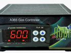
The Qubit Gas Control Systems employ the A365 Gas Controller in regulating the solenoid valve and control the content of gases such as CO2, O2, CH4, H2O vapour inside a chamber, for example a plant growth chamber or animal cabinet. This system can be applied to control CO2 and 13CO2 levels inside a chamber, or to maintain elevated or reduced O2 levels. Precise control of water vapour in the growth cabinet is also possible with this system.
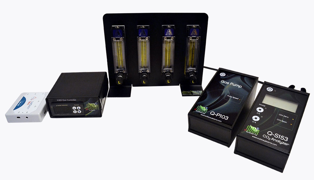
The gas control system is composed of the Gas Controller A365, the Solenoid valve, the gas analyzer (CO2, O2 H2, CH4, water vapour analyzer), a gas pump for sampling from the chamber and delivery to the gas analyzer for measurement. At least three rotameter flow meters, and a nafion RH equilibrator are also employed in the system. The stability of the gas concentration is monitored and logged via data interface and software.
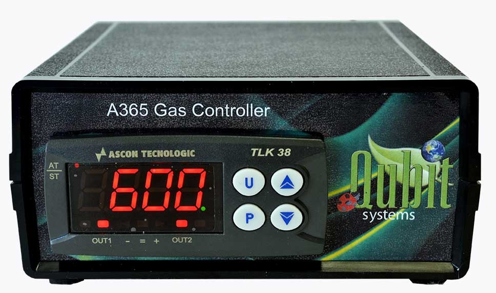
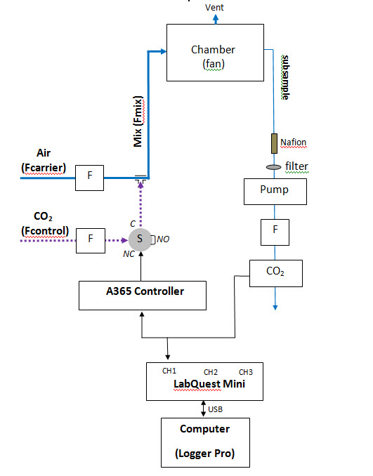
The Qubit A365 Gas Controller set to PID mode energizes a 3-way solenoid valve to inject control gas (e.g. CO2) into the carrier gas (e.g. air) to regulate the CO2 level in a chamber. The levels of sub-sampled control gas are measured by Qubit’s CO2 analyzer. A feedback signal is sent back to the Gas Controller A365 which activates or deactivates the solenoid valve to control the flow, and thereby the chamber level, of CO2.
Features
- Control of gas concentrations in a chamber via feedback control of a solenoid
- Ability to cope with slow changes in the controlled gas due to plant or animal activity
- Flexible system that can be used for control of various gases (by changing the gas analyzer)
Applications
- photosynthesis research
- animal respiration research
- plant growth studies
- environmental control
- insect research
- algal research
- A365 Gas Controller
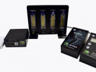
- Gas Analyzer (CO2, O2, CH4, H2O vapour)
- Q-P103 Gas Pump (1LPM)
- Flowmeters (x3) range depends on the system application
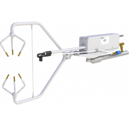
- Solenoid valve mounted on the back of Flowmeter Manifold
- B301 Nafion RH Equilibrator
- Data interface and software
Schematic diagram of CO2 Control System (F=flowmeter, S=Solenoid,NO=Normally open, NC=Normally closed, C=Common, Heavy lines = gas flow, light lines=electrical connections)
- IIacqua AN, Kirby AM, Pamenter ME (2017) Behavioural responses of naked mole rats to acute hypoxia and anoxia. Royal Society Biology Letters Physiology