With an AVW200 vibrating-wire analyzer module, your data logger can measure vibrating-wire strain gages, pressure transducers, piezometers, tiltmeters, crackmeters, and load cells. These sensors are used in a wide variety of structural, hydrological, and geotechnical applications because of their stability, accuracy, and durability.
The AVW200 uses vibrating-wire spectral-analysis technology (VSPECT™). VSPECT observes the incoming sensor signal, performs a Fourier transform and a spectral analysis (transforming the time series into indivdual sinusoidal components in the frequency spectrum), and determines the sensor frequency by identifying the largest signal in the acceptable range while filtering out environmental and electrical noise.
The AVW200 analyzer module also provides many self-checking diagnostics such as vibrating-element signal strength, signal-to-noise ratio, vibrating-element signal decay ratio, and incorrect signal response. These diagnostics can be running in the background to give continual feedback of the condition for each sensor.
| -NOTE- | Electrical specifications are valid over a -25° to +50°C range unless otherwise specified. Non-condensing environment required. |
| Number of Vibrating-Wire Sensors Measured | Up to 2 vibrating-wire sensors can be connected to the analyzer module. Additional sensors can be measured by using an AM16/32-series multiplexer. |
| Power Requirements | 9.6 to 16 Vdc |
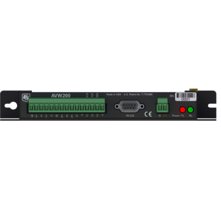
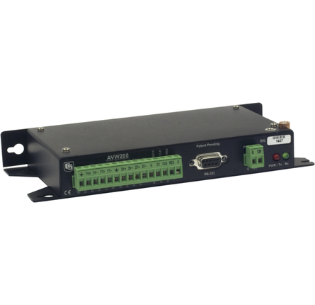
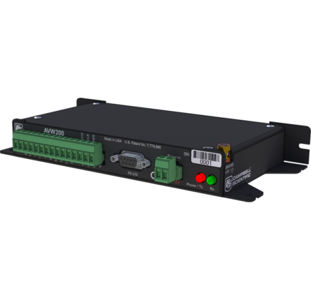
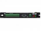
| Analog Input/Outputs | 2 differential (DF) vibrating-wire measurements (V+ and V-) and 2 single-ended (SE) ratiometric resistive half-bridge measurements (T+ and T-) for vibrating-wire sensor's onboard temperature sensor. |
| Digital Control Ports | 3 digital control ports (C1 – C3)
|
| RS-232 Port | 1 9-pin RS-232 port (for connecting to a data logger COM port) |
| Measurement Resolution | 0.001 Hz RMS (±250 mV differential input range; -55° to +85°C) |
| Measurement Accuracy | ±0.013% of reading (±250 mV differential input range; -55° to +85°C) |
| Input Voltage Range | ±250 mV (differential) for vibrating-wire inputs |
| Common Mode Range | ±25 V |
| Baud Rates | Selectable from 1200 to 38.4 kbps. (ASCII protocol is one start bit, one stop bit, eight data bits, and no parity.) |
| Memory |
|
| CE Compliance Standards to which Conformity Is Declared | IEC61326:2002 |
Typical Current Drain @ 12 Vdc
| Quiescent, Radio Off | ~0.3 mA |
| Radio Duty Cycling 1 s | ~3 mA (includes quiescent current) |
| Radio Always On | ~26 mA (radio transmit current 100 mA) |
| Active RS-232 Communication | ~6 mA (3 s after communication stops, the current will drop to the quiescent current.) |
| Measurement | ~25 mA (averaged over the 2 s) |