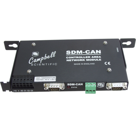
The SDM-CAN allows a Campbell Scientific data logger to sample data directly from a CANbus communication network. This allows testing and verification of CANbus-based data alongside measurements made independently via the data logger's input channels. The SDM-CAN also supports transmission of data onto a CANbus network.
Benefits and Features
- Supports various CAN modes
- Uses latest Philips CAN controller
- Can be used in many networking applications, including vehicle testing
CANbus data can be stored (and synchronized) with other data values measured directly by the data logger, allowing testing and verification of CANbus-based data alongside measurements made independently via the data logger's input channels. The SDM-CAN also supports transmission of data onto a CANbus network.
The SDM-CAN uses the latest Philips SJA1000 CAN controller clocked at 16 MHz; CAN 2.0A and 2.0B active and passive modes are supported, which includes SAE J1939. The CANbus protocol is used in a number of networking applications, including vehicle data acquisition systems (VDAS).
The SDM-CAN can act as a passive “listen-only” device, poll remote devices for data, or act as a sensor. To poll remote devices it sends or responds to Remote Frame Requests. It acts as a sensor by sending data packets to the CANbus network. The SDM-CAN supports baud rates up to 1 MB (1 M, 800 k, 500 k, 250 k, 125 k, 50 k, 20 k, and lower). Non-standard baud rates may be possible. CAN data frames can also be built and sent.
The data logger enables individual modules through an addressing scheme; up to 15 SDM-CANs can be connected to one data logger.
| Function | Allows a data logger to sample data directly from a CANbus communication network. Uses latest CAN controller. |
| Number of Channels | 1 |
| Operating Temperature | Tested from -40° to +80°C. |
| Operating Voltage | 7 to 26 Vdc |
| Isolation | Optional (switch-selectable) galvanic isolation between the data logger and the CANbus. The minimum isolation breakdown is 50 V; this barrier is for signal isolation only (that is, it is not a safety barrier). |
| Controller | Uses the latest Philips SJA1000 CAN controller clocked at 16 MHz. |
| CANbus Physical Connection | Conforms to CIA draft standard 102 version 2, 9-pin D connector. (The interface will differ from this standard only with respect to pin 9, which outputs 5 Vdc instead of 7 to 13 Vdc.) |
| Screw Terminal Block | A three-way, unpluggable screw terminal block for CAN High, Low, and G is provided. |
| Safety | For safety reasons, can disable CANbus transmit and acknowledge via a jumper (for example, for in-vehicle, listen-only monitoring) |
Typical Current Consumption
| Active in Self-Powered, Isolated Mode |
|
| Active, Non-Isolated |
|
| Standby | < 1 mA (with or without isolation) |
| Communications with Data Logger | 50 mA |
| RS-232 Port Active | 50 mA |