Senseca
LPNET07 Net Irradiance Meter for Accurate Outdoor Energy Balance Monitoring
LPNET07 net irradiance meter for outdoor energy balance and meteorological monitoring.
Net irradiance measuring range ±2000 W/m²
Spectral range 0.2…100 µm with 180° viewing angle for both sensors
Passive thermopile sensor with PTFE-coated receiving surfaces
Operating temperature -40…+80 °C
Fixed 5 m cable, factory calibrated with calibration report
Overview
The Senseca LPNET07 is a net irradiance meter designed for outdoor energy balance monitoring and meteorological applications. It measures the difference between radiation received by its upper and lower surfaces using a thermopile sensor based on the Seebeck effect. The instrument provides a measuring range of ±2000 W/m², a spectral range of 0.2…100 µm and a 180° viewing angle for each of the upper and lower sensors.
The radiometer features PTFE-coated receiving surfaces for long-term outdoor use in all weather conditions and operates at temperatures from -40 to +80 °C. As a passive instrument, it requires no external power supply and delivers a low-level voltage output through a fixed 5 m cable for connection to a voltmeter or data logger. Each unit is factory calibrated and supplied with a calibration report.
Typical Applications
Net irradiance monitoring in meteorological applications
Outdoor surface energy balance studies
Indoor radiant temperature measurement according to ISO 7726
Key Features
Thermopile sensor based on the Seebeck effect
Dual PTFE-coated receiving surfaces for outdoor radiation measurement
Net irradiance measuring range ±2000 W/m²
Spectral range 0.2…100 µm
180° viewing angle for each sensor
Typical sensitivity 10 µV/(W/m²)
Response time (95%) less than 60 seconds
Operating temperature −40…+80 °C
Passive operation without external power supply
Low-level voltage output with typical sensor impedance of 2…4 Ω
Fixed 5 m UV-resistant connection cable
Factory calibrated and supplied with calibration report
Benefits
Net radiation balance measured with one instrument
Broad spectral coverage for solar and terrestrial radiation monitoring
Suitable for long-term outdoor monitoring with PTFE-coated receiving surfaces
No external power supply required for operation
Easy connection to a voltmeter or data logger through a fixed 5 m cable
Factory calibrated and supplied with a calibration report
Specifications
Measurement | |
|---|---|
Measured quantity | Net irradiance |
Measuring principle | Thermopile sensor based on the Seebeck effect |
Measuring range | ±2000 W/m² |
Spectral range | 0.2…100 µm |
Typical sensitivity | 10 µV/(W/m²) |
Response time (95%) | <60 s |
Upper sensor viewing angle | 180° |
Lower sensor viewing angle | 180° |
Electrical | |
|---|---|
Power supply | Not required (passive sensor) |
Output signal | Voltage signal, typically a few mV |
Typical sensor impedance | 2…4 Ω |
Recommended reading instrument | Voltmeter or data logger |
Recommended reading resolution | 1 µV |
Connection cable | Fixed 5 m UV-resistant cable |
Cable configuration | 2 wires plus shield |
Positive output (+Vout) | Red wire |
Negative output (−Vout) | Blue wire |
Cable shield / radiometer housing | Black wire |
Environmental | |
|---|---|
Operating temperature | −40…+80 °C |
Outdoor suitability | Suitable for outdoor use in all weather conditions |
Mechanical | |
|---|---|
Housing material | Anodized aluminium alloy |
Fixing shaft material | Anodized aluminium alloy |
Sensitive area material | Aluminium alloy with PTFE coating |
Bird spike material | Stainless steel |
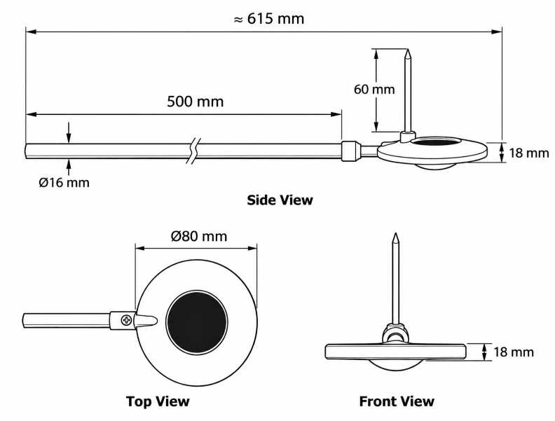
Fixing shaft dimensions | Ø16 × 500 mm |
Weight | Approximately 0.35 kg |
Calibration | |
|---|---|
Factory calibration | Factory calibrated |
Calibration method | Comparison with a reference net radiometer using a solar simulator with a parallel light beam |
Calibration documentation | Calibration report supplied |
Calibration checking | Annual checking highly recommended |
Installation | |
|---|---|
Minimum installation height | 1.5 m above ground |
Orientation – Northern Hemisphere | Toward the south |
Orientation – Southern Hemisphere | Toward the north |
Installation location | Free from shadows cast by buildings, trees and other obstructions |
Grounding | Local grounding of the metallic housing preferred |
Drawing

Downloads
| LPNET07 Datasheet | DownloadLPNET07 Datasheet |
|---|---|
| LPNET07 User Manual | DownloadLPNET07 User Manual |
| LPNET07 CE Declaration of Conformity | DownloadLPNET07 CE Declaration of Conformity |
Related Products

Senseca
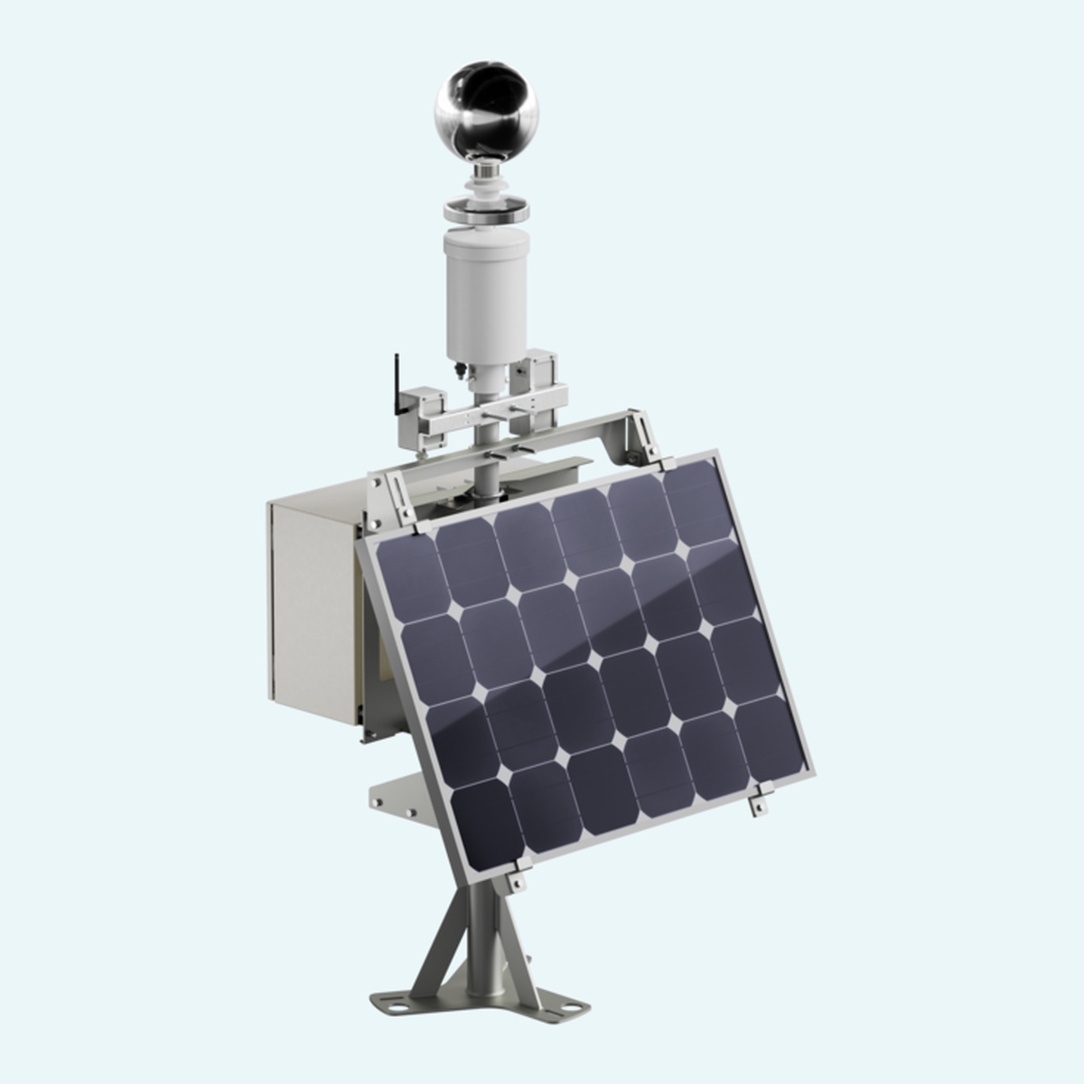
BTD-200 Lightning Warning System
Self-contained lightning warning system detecting cloud-to-ground, intra-cloud and cloud-to-cloud lightning up to 35 km, with early overhead warning, 3 relays…
Learn More
Senseca
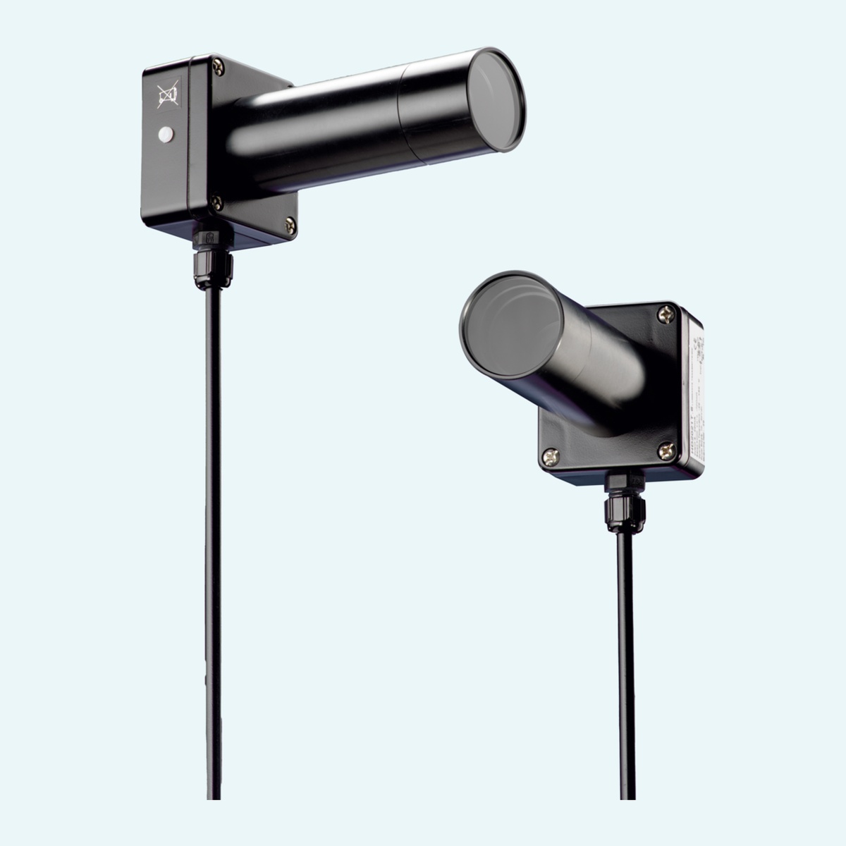
BTD-1 Thunderstorm Warning System
Standalone thunderstorm warning system detecting lightning up to 35 km (83 km option) from the quasi-electrostatic field, with early warning, Severe Storm…
Learn More
Senseca
HD2021T6 - HD2021T7 Luminance Transmitters
Luminance transmitters for tunnel and road lighting control, converting cd/m² into 0…10 V or 4…20 mA, with ranges up to 200 kcd/m², IP52 and versions for Lv…
Learn More
Senseca
ALS-2 Ambient Light Sensor
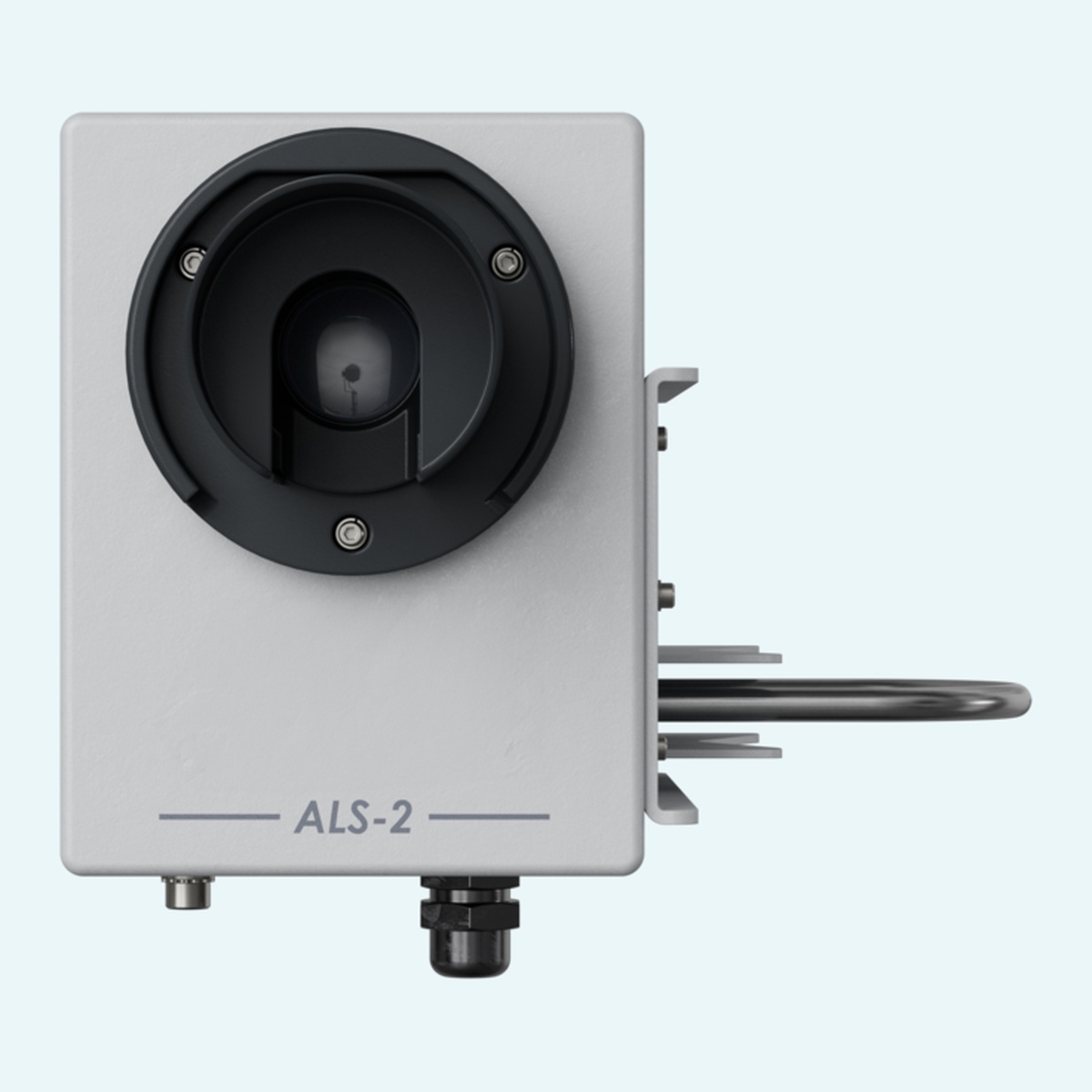
Ambient light sensor for runway visual range (RVR) systems, measuring background luminance from 0 to 40,000 cd m-2, with RS232/RS422/RS485 outputs and heated…
Learn More