

Senseca
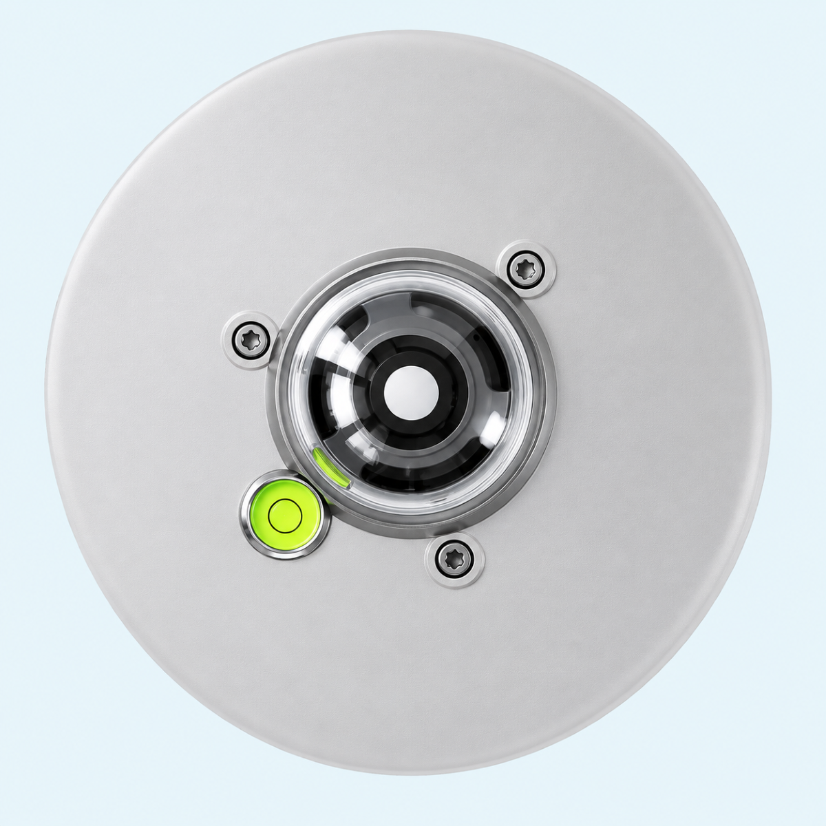
LPR10 Class A Pyranometer
Fast Response Spectrally Flat Class A pyranometer for global solar irradiance measurement.
Measuring range −200…4000 W/m² and 95% response time < 0.3 s
Thermopile sensor with 285…2850 nm spectral range (50%)
Isolated RS485 Modbus-RTU output
Integrated heater, tilt sensor and internal temperature, humidity and pressure diagnostics
7…30 Vdc power supply, IP67 protection
Overview
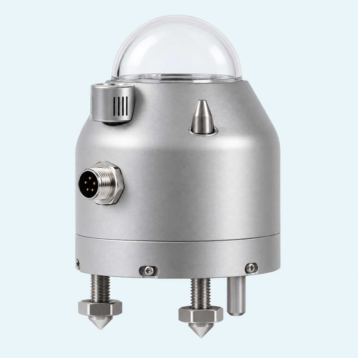
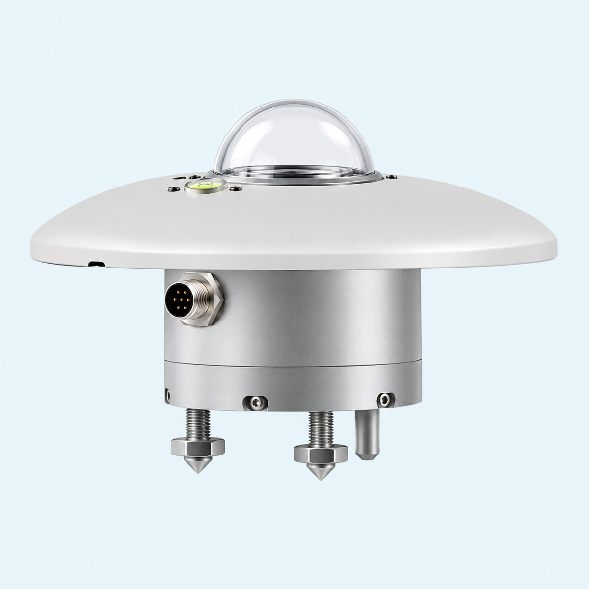
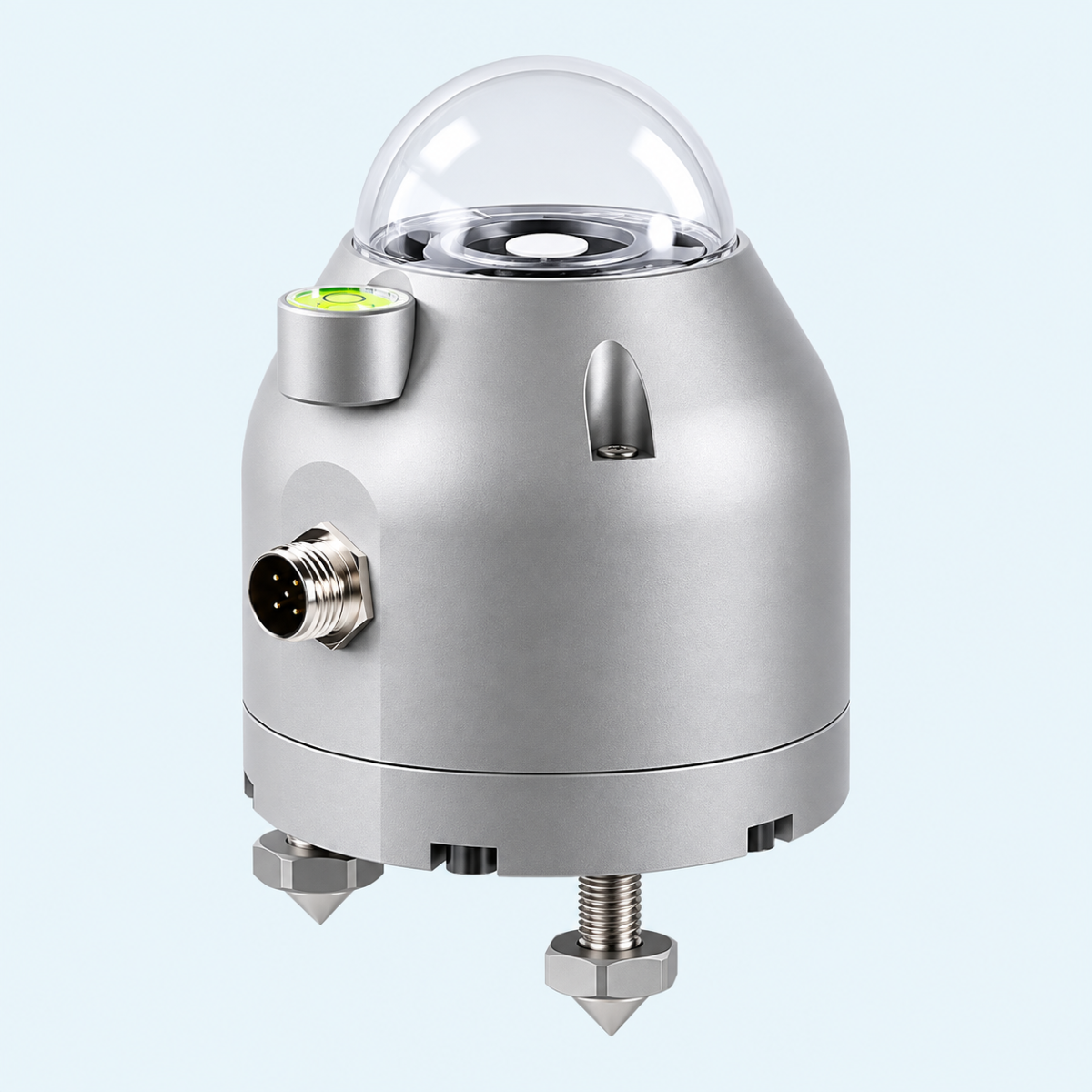
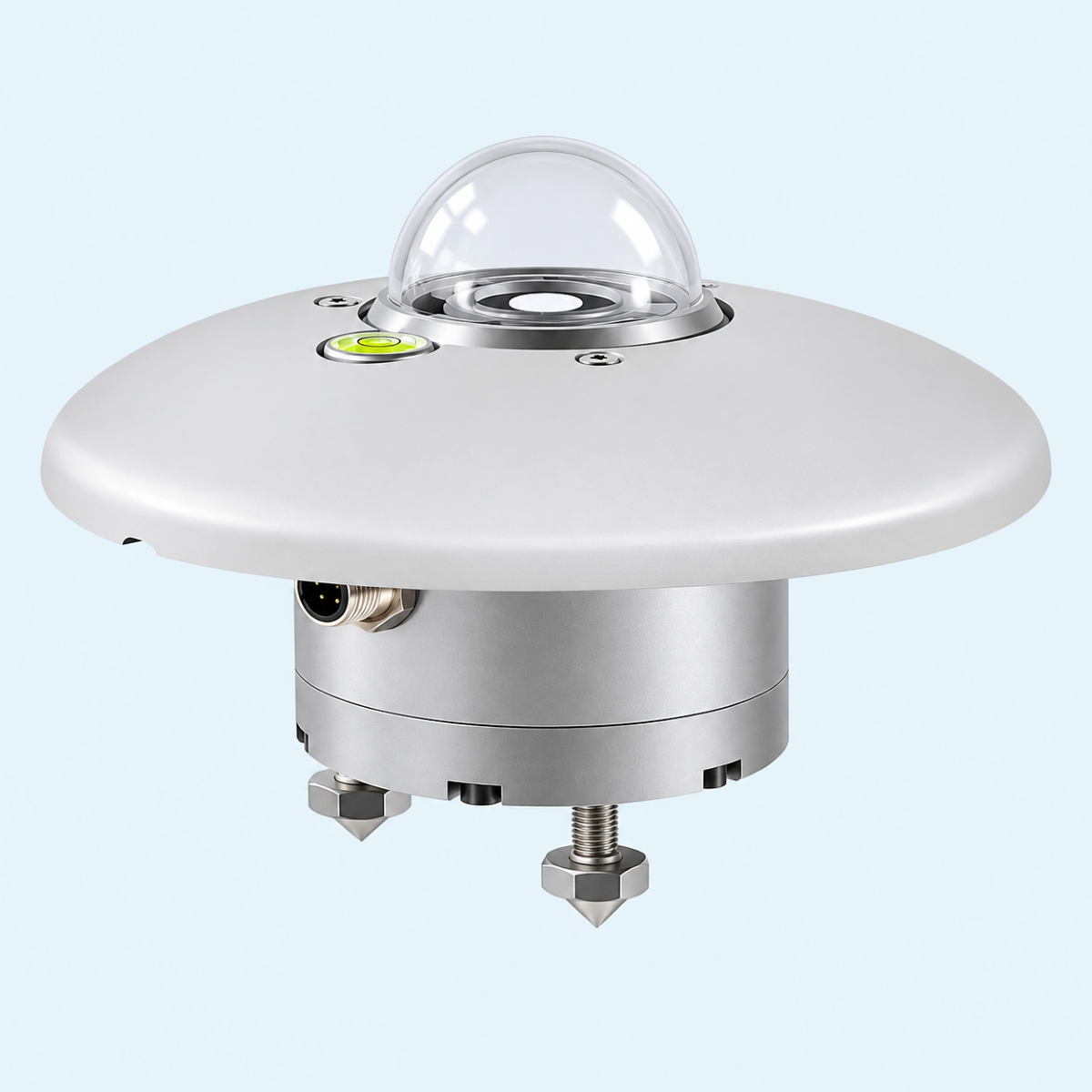
The Senseca LPR10M0T is a Fast Response Spectrally Flat Class A pyranometer according to ISO 9060:2018, designed to measure global solar irradiance on a flat surface, including direct and diffuse solar radiation. It uses a thermopile sensor with a measuring range of −200…4000 W/m², a spectral range of 285…2850 nm (50%) and a 95% response time of less than 0.3 seconds.
The pyranometer features an integrated heater with automatic, always-on and always-off operating modes to prevent dew and frost formation. Internal temperature, relative humidity and pressure sensors provide diagnostic monitoring of operating conditions, while an integrated tilt sensor enables continuous installation stability monitoring. Adjustable feet and a bubble level facilitate accurate horizontal positioning.
It provides an isolated RS485 Modbus-RTU output for system integration, with DATA sense software supporting configuration, real-time measurement monitoring and data logging. The instrument operates on a 7…30 Vdc power supply, features IP67 protection and is supplied with an ISO 17025-accredited calibration certificate.
Typical Applications
Photovoltaic (PV) system performance monitoring
Meteorological solar radiation measurement
Environmental monitoring and studies
Solar radiation research and analysis
Key Features
Fast Response Spectrally Flat Class A according to ISO 9060:2018
Thermopile sensor for global solar irradiance measurement
Measuring range −200…4000 W/m²
Spectral range (50% response): 285…2850 nm
Response time (95%): < 0.3 s
Resolution 0.1 W/m²
Isolated RS485 Modbus-RTU output
Integrated heater with automatic, always-on and always-off operating modes
Internal temperature, relative humidity and pressure diagnostic sensors
Integrated tilt sensor with 0°…180° measuring range
Adjustable feet and bubble level with < 0.2° accuracy
DATAsense software for configuration, real-time monitoring and data logging
7…30 Vdc power supply
IP67 protection and −40…+80 °C operating temperature
Factory calibration according to ISO 9847:2023, with ISO 17025-accredited calibration certificate
Benefits
Fast-response, Class A solar irradiance measurement for reliable monitoring
Integrated heater helps prevent dew and frost to maintain measurement reliability
Built-in diagnostics support early identification of potential maintenance needs
Continuous tilt monitoring helps detect unwanted changes in installation position
Easy installation with adjustable feet and integrated bubble level
Isolated RS485 Modbus-RTU output enables integration with existing monitoring systems
DATAsense software simplifies configuration, real-time monitoring and data logging
ISO 17025-accredited calibration certificate provides documented calibration traceability
IP67 protection supports reliable operation in outdoor environments
Specifications
Solar Radiation Measurement | |
|---|---|
Measured quantity | Global solar irradiance (direct and diffuse solar radiation) |
Sensor | Thermopile |
Classification | Fast Response Spectrally Flat Class A |
Classification standard | ISO 9060:2018 |
Measuring range | −200…4000 W/m² |
Resolution | 0.1 W/m² |
Spectral range (50%) | 285…2850 nm |
Viewing angle | 2π sr |
Response time (95%) | < 0.3 s |
Performance Specifications (ISO 9060:2018) | |
|---|---|
Zero offset (a): response to 200 W/m² thermal radiation | Absolute value < 1 W/m² |
Zero offset (b): response to 5 K/h ambient temperature change | Absolute value < 1 W/m² |
Zero offset (c): total zero offset including (a), (b) and other sources | Absolute value < 4 W/m² |
Long-term instability (1 year) | Absolute value < 0.5% |
Non-linearity | Absolute value < 0.2% |
Directional response (up to 80° with 1000 W/m² beam) | Absolute value < 10 W/m² |
Spectral error | Absolute value < 0.2% |
Temperature response (−10…+40 °C) | Absolute value < 0.5% |
Tilt response | Absolute value < 0.4% |
Internal Temperature Diagnostic Sensor | |
|---|---|
Measuring range | −40…+80 °C |
Resolution | 0.1 °C |
Accuracy | ±0.5 °C (0…60 °C) |
Internal Relative Humidity Diagnostic Sensor | |
|---|---|
Measuring range | 0…100% RH |
Resolution | 0.1% RH |
Accuracy | ±3% RH at 25 °C and 20…80% RH |
Internal Pressure Diagnostic Sensor | |
|---|---|
Measuring range | 500…1100 hPa |
Resolution | 0.1 hPa |
Accuracy | ±1 hPa (0…60 °C) |
Tilt Sensor | |
|---|---|
Measuring range | 0°…180° |
Resolution | 0.1° |
Accuracy | < 0.5° |
Electrical and Communication | |
|---|---|
Output | Galvanically isolated RS485 Modbus-RTU |
Power supply | 7…30 Vdc |
Power consumption (heater ON) | 2 W |
Power consumption (heater OFF) | 0.3 W |
Electrical connection | 5-pole M12 connector |
Modbus address range | 1…247 |
Default Modbus address | 1 |
Supported baud rates | 9600, 19200, 38400, 57600, 115200 bps |
Default baud rate | 19200 bps |
Default serial communication format | 8E1 |
Integrated Heater | |
|---|---|
Heater | Integrated |
Operating modes | Always ON, Always OFF, AUTO |
AUTO mode activation threshold | +10 °C |
AUTO mode deactivation threshold | +40 °C |
Factory default operating mode | Always OFF |
Mechanical and Environmental | |
|---|---|
Housing material | Anodized aluminium |
Protection screen material | ASA |
Dome material | Optical glass |
Weight | Approximately 650 g |
Operating temperature | −40…+80 °C |
Operating relative humidity | 0…100% RH |
Maximum operating altitude | 6000 m |
Protection degree | IP67 |
Bubble level accuracy | < 0.2° |
Mean time between failures (MTBF) | > 10 years |
Physical Dimensions | |
|---|---|
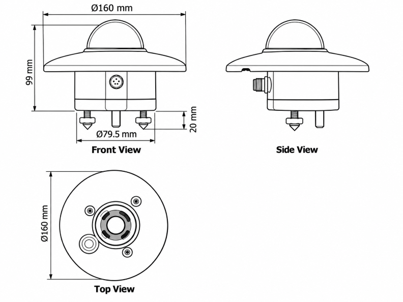
Overall protection screen diameter | Ø160 mm |
Main body diameter | Ø79.5 mm |
Height from top of dome to underside of main body | 99 mm |
Mounting feet extension below main body | 20 mm |
Installation and Mounting | |
|---|---|
Fixing holes | 4 × M5 |
Horizontal positioning | Adjustable feet and integrated bubble level |
Installation monitoring | Integrated tilt sensor |
Calibration | |
|---|---|
Factory calibration standard | ISO 9847:2023 (Type A1) |
Calibration method | Comparison with a reference pyranometer |
Reference calibration | Reference sample calibrated annually at WRC (World Radiation Center) |
Calibration certificate | ISO 17025-accredited calibration certificate |
Additional calibration measurements | Temperature response and directional response |
Configuration and Software | |
|---|---|
Configuration software | DATAsense PC application |
Software functions | Configuration, real-time measurement monitoring, graphical irradiance display and data logging |
Alternative configuration method | ASCII proprietary protocol |
Modbus configuration | Holding Registers for selected parameters |
Configurable serial parameters | Modbus address, baud rate, parity and stop bits |
Configurable alarm thresholds | Operating time, internal temperature, relative humidity and pressure |
Configurable temperature units (Modbus) | °C, °F, K |
Temperature unit (ASCII proprietary protocol) | °C |
Supplied Items and Optional Accessories | |
|---|---|
Solar radiation protection screen | Supplied |
M12 female free connector | Supplied if optional cable is not ordered |
Calibration certificate | ISO 17025-accredited calibration certificate, supplied |
DATAsense PC application | Downloadable from manufacturer's website |
LPS1 mounting bracket | Optional; for Ø30…50 mm mast, horizontal or vertical installation |
LPS5 adjustable holder | Optional; for inclined installation on Ø30…50 mm mast |
Installation cables | Ordered separately |
Drawing
Downloads
| LPR10 Datasheet | DownloadLPR10 Datasheet |
|---|---|
| LPR10 User Manual | DownloadLPR10 User Manual |
| LPR10 CE Declaration of Conformity | DownloadLPR10 CE Declaration of Conformity |
Related Products
Senseca
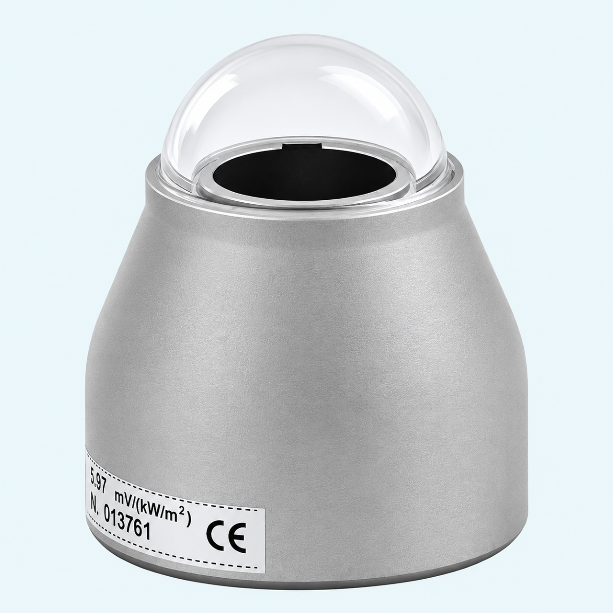
LPPYRA-Lite Class C Pyranometer
Compact Class C thermopile pyranometer for PV and solar monitoring.
Learn More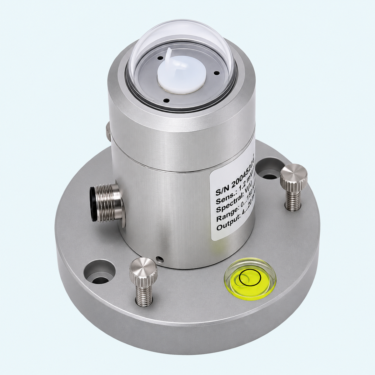
Senseca
LPPHOT03 Photometric Probe
LPPHOT03 outdoor illuminance probe with photopic V(λ) response, cosine correction and individual calibration.
Learn More
Senseca
LPNET14 4-Component Net Irradiance Meter
Four-component net irradiance meter measuring global and reflected solar radiation plus sky and ground infrared radiation.
Learn More
Senseca
LPNET07 Net Irradiance Meter
LPNET07 net irradiance meter for outdoor energy balance monitoring.
Learn More