WETEC

Senseca

HD402 Pressure Transmitter


Relative and differential pressure transmitter and relay switch for air and dry gases.

  • Ranges from ±50 Pa up to ±200 kPa, with a temperature-compensated piezoresistive sensor
  • Output by model: 0…10 V, 0/4…20 mA, 2-wire 4…20 mA, RS485 Modbus-RTU or SPDT relay
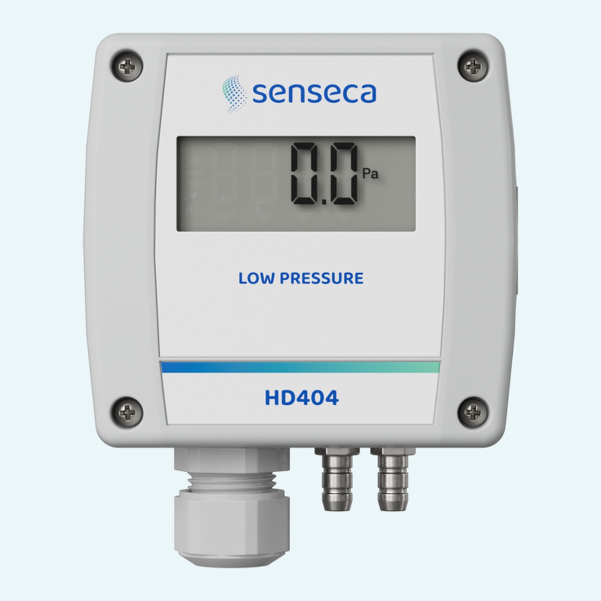
  • Optional 4-digit LCD, IP65 ABS housing and installation in any position
Quantity
1

Overview

The Senseca HD402 series consists of pressure transmitters and pressure ON/OFF relay switches for relative pressure (to atmosphere) or differential pressure measurement in air and non-aggressive dry gases. Depending on the model, it covers ranges from 50 Pa up to 200 kPa and uses a high-stability silicon piezoresistive sensor with temperature compensation for excellent linearity, repeatability and long-term stability.

The series is factory-calibrated and ready to use, and is available with several output types: 0…10 V and 0/4…20 mA active, 2-wire 4…20 mA, RS485 Modbus-RTU, or an ON/OFF relay switch with SPDT contact. A 4-digit LCD is optional for local reading, and the relay switch versions always include the display, a front red LED and an internal buzzer. The IP65 ABS housing is insensitive to mounting orientation and can be wall-mounted in any position.

Typical applications

  • HVAC pressure monitoring
  • Clean air applications
  • Dry gas applications
  • Industrial environments (wall mounting)

Key Features

  • Relative (to atmosphere) or differential pressure measurement
  • Ranges from ±50 Pa up to ±200 kPa, depending on the model
  • Piezoresistive sensor with temperature compensation
  • Output by model: 0…10 V, 0/4…20 mA, 2-wire 4…20 mA, RS485 Modbus-RTU or SPDT relay
  • Optional 4-digit LCD (always included on relay versions)
  • Relay versions with front red LED and internal buzzer for alarm signalling
  • Configuration by PC connection, dip switches or internal buttons (relay models)
  • Auto-zero on the low-range relay model HD402TR1L

Benefits

  • Stable readings over time, thanks to the temperature-compensated sensor and long-term stability specifications
  • The output can be matched to your controller, PLC or BMS, from analog to Modbus-RTU or relay
  • Factory-calibrated and ready to use, with quick configuration by PC or dip switches
  • Insensitive to mounting orientation, so it can be installed in any position

Specifications

MEASUREMENT


Sensor

Piezoresistive, high stability

Measuring range

±50 Pa up to ±200 kPa, depending on the model (see Measuring ranges)

Resolution

See Measuring ranges

Response time

0.5 s for the display updating. Configurable 0.125, 1, 2 or 4 s for analog and RS485 output

Zero calibration

Automatic for HD402TR1L, manual for the other models


ACCURACY


Accuracy basis

FSS = nominal range (= 2 x f.s. high range)

HD402TR1

±(0.8% measure + 0.5 Pa) @ 0…50°C

HD402xT1

±1.5% FSS @ 25°C / ±3% FSS @ 0…50°C

HD402xx2

±0.75% FSS @ 25°C / ±1% FSS @ 0…50°C

HD402xx3/4/5

±1% FSS @ 0…50°C

Long-term stability, HD402TR1 (1000 h @ 25°C)

±0.2 Pa with auto-zero

Long-term stability, HD402xT1 / HD402xx2

±0.5% FSS

Long-term stability, HD402xx3

±0.35% FSS

Long-term stability, HD402xx4/5

±0.25% FSS

Overpressure limit, HD402xx1/2/3

50 kPa

Overpressure limit, HD402xx4

200 kPa

Overpressure limit, HD402xx5

400 kPa


MEASURING RANGES


HD402...1

±50 / 100 / 250 Pa, resolution 0.1 Pa

HD402...2

±250 / 500 / 1000 Pa, resolution 1 Pa

HD402...3

±2.5 / 5 / 10 kPa, resolution 0.01 kPa

HD402...4

±25 / 50 / 100 kPa, resolution 0.1 kPa

HD402...5

±50 / 100 / 200 kPa, resolution 0.1 kPa

Other units

For the corresponding measuring ranges and resolution in mmH2O, inchH2O and mbar, refer to the manual


OUTPUT


HD402T…

0…10 Vdc or active 0/4…20 mA

HD402AT…

2-wire 4…20 mA

HD402ST…

RS485 Modbus-RTU

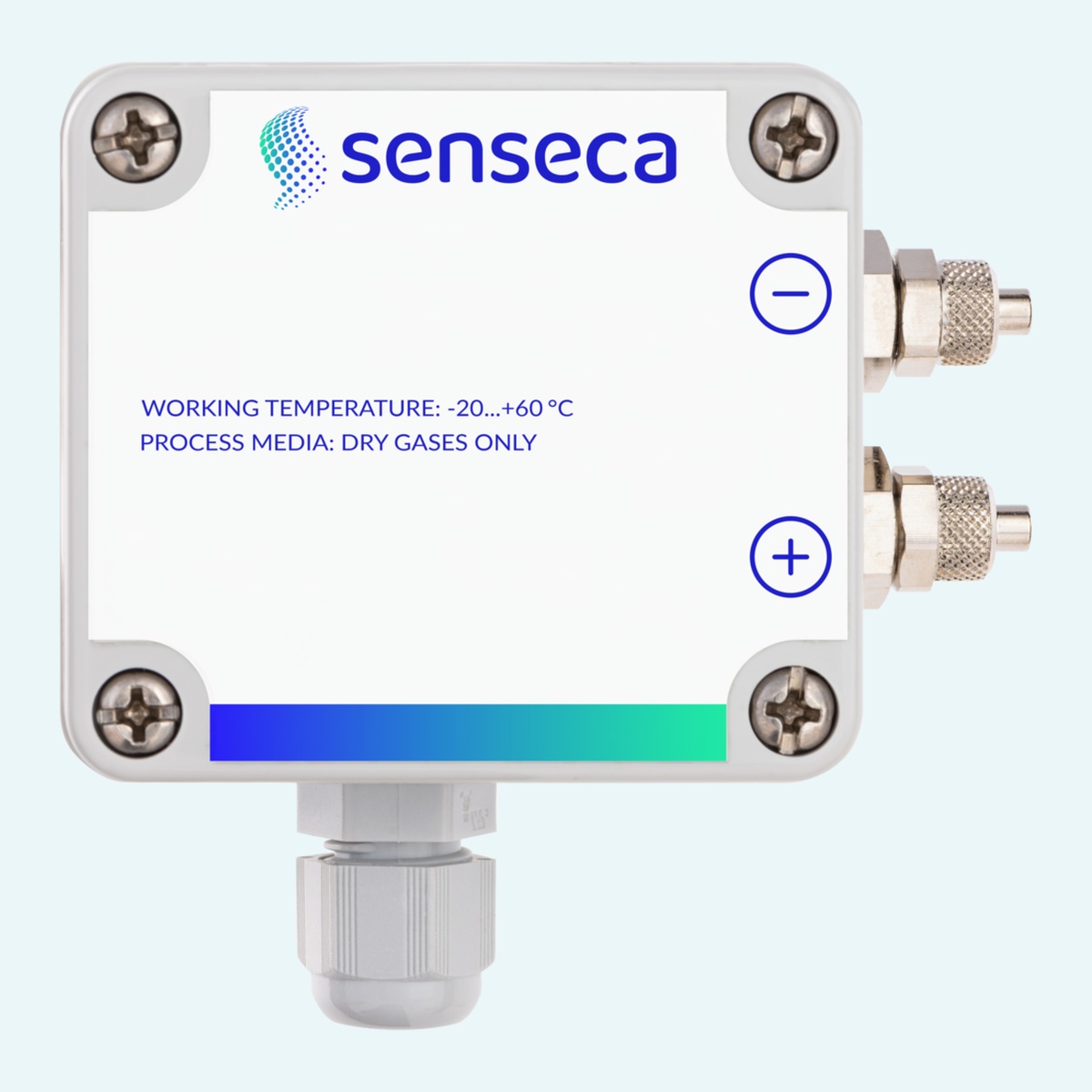
HD402TR…

ON/OFF relay switch with SPDT contact

Alarm (HD402TR only)

Front red LED and internal buzzer

Analog output models

Selectable full scale (high / intermediate / low range) and unipolar (0…+f.s.) or bipolar (-f.s…+f.s.) output scaling

Connection to PC

Modbus model: RS485 serial port, connection to a USB port using an RS485 adapter. All other models: RS232 serial port, connection to a USB port using the CP27 cable


POWER REQUIREMENT


HD402T…

24 Vac ±10% or 18…40 Vdc

HD402AT… and HD402ST…

12…30 Vdc

HD402TR…

24 Vac ±10% or 15…36 Vdc

Absorption

<1 W @ 24 Vdc (HD402T…, HD402AT…, HD402TR…)

Electrical connections

Screw terminal block, max 1.5 mm², PG9 cable gland


ENVIRONMENTAL


Operating conditions

-10…+60°C / 0…95 %RH

Storage temperature

-20…+70°C

Compatible media

Only air and non-aggressive dry gases

Protection degree

IP65


MECHANICAL


Materials

Housing: ABS. Pressure connections: nickel-plated brass

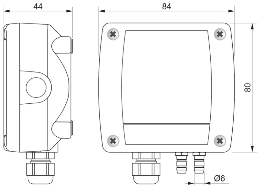
Pressure connections

Ø 6 mm

Dimensions

See drawing

Mounting

Two Ø 3 mm rear holes, any installation position


ORDERING CODES


Code structure

HD402 + measuring range (1…5) + type of output (T, AT, ST, TR) + display (blank or L)

Display

Blank = without LCD (except HD402TR…). L = with LCD

Measuring range 1

±250 Pa / 25 mmH2O / 1 inchH2O / 2.5 mbar

Measuring range 2

±1000 Pa / 100 mmH2O / 4 inchH2O / 10 mbar

Measuring range 3

±10 kPa / 50 mmHg / 1.5 PSI / 100 mbar

Measuring range 4

±100 kPa / 500 mmHg / 15 PSI / 1000 mbar

Measuring range 5

±200 kPa / 1000 mmHg / 30 PSI / 2000 mbar

Type of output

T = 0…10 V and 0/4…20 mA active analog output. AT = 2-wire 4…20 mA analog output. ST = RS485 Modbus-RTU digital output. TR = ON/OFF relay switch output

Supplied with

2 m of silicone tubing (Ø 5 mm internal / Ø 8 mm external) and two plastic fittings for ducts

Ordered separately

PC connecting cable

Drawing

HD402_drawing_small

Downloads

HD402 Family Datasheet (EN) DownloadHD402 Family Datasheet (EN)
HD402 Family User Manual (EN) DownloadHD402 Family User Manual (EN)