WETEC

Senseca

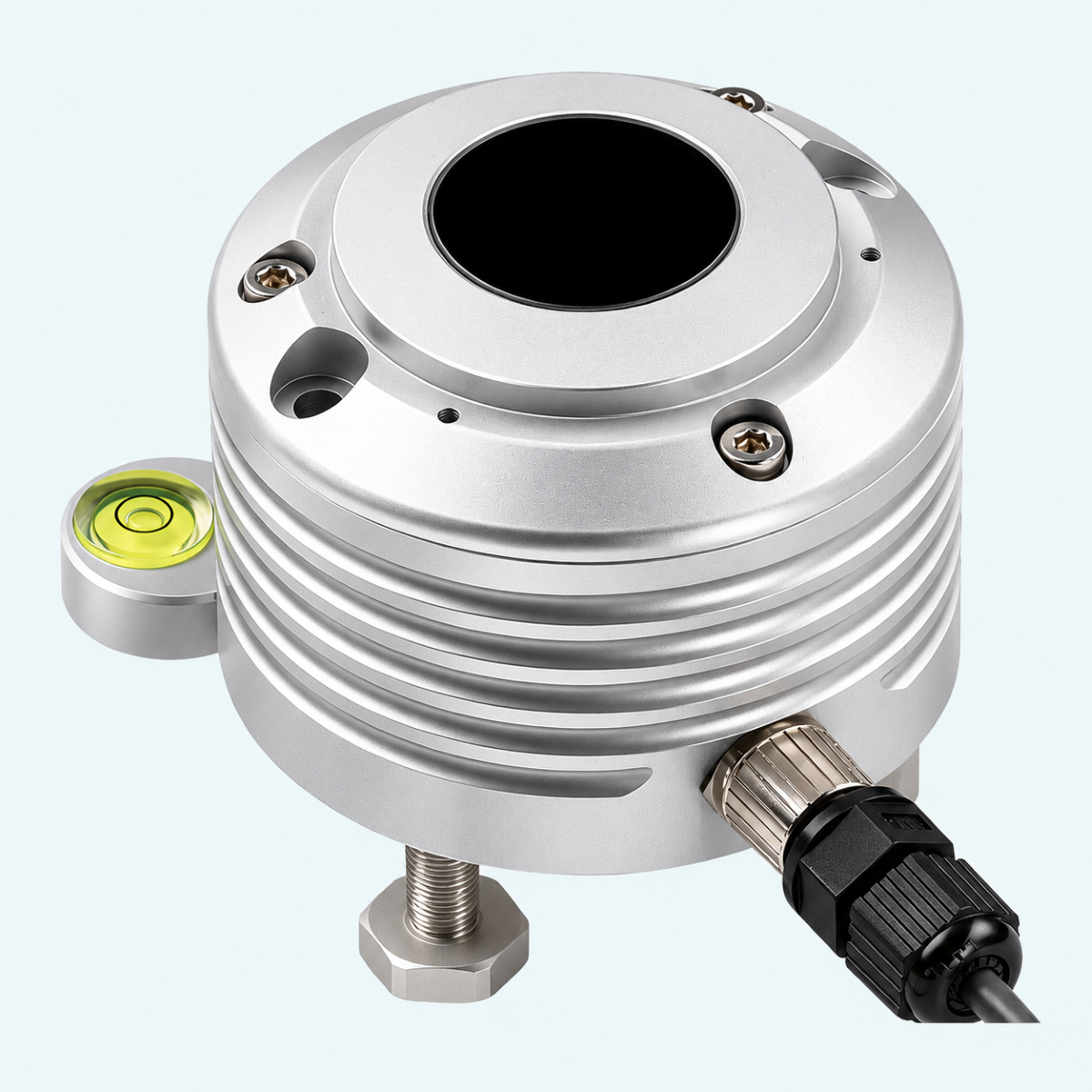
LPUVA03 Radiometric Probe


LPUVA03 UVA Irradiance Probe for Outdoor Monitoring

  • Measures UVA irradiance in the 315…400 nm spectral region

  • Measurement range of 0…200 W/m² for normalized and RS485 output versions

  • Typical sensitivity of 70…200 µV/(W/m²)

  • Passive mV, 4…20 mA, 0…10 Vdc or RS485 MODBUS-RTU output options

  • Individually calibrated with diffuser for cosine correction and protective dome

  • Operating temperature of −20…+60 °C

  • M12 connector with optional 2, 5 or 10 m cables

Quantity
1

Overview

The Senseca LPUVA03 is a radiometric probe designed for outdoor monitoring of ultraviolet A (UVA) irradiance in the 315…400 nm spectral region. It uses a photodiode that is insensitive to visible and infrared light, with a peak spectral response at 365 nm. The probe has a typical sensitivity of 70…200 µV/(W/m²), while versions with normalized or RS485 outputs provide a measurement range of 0…200 W/m².

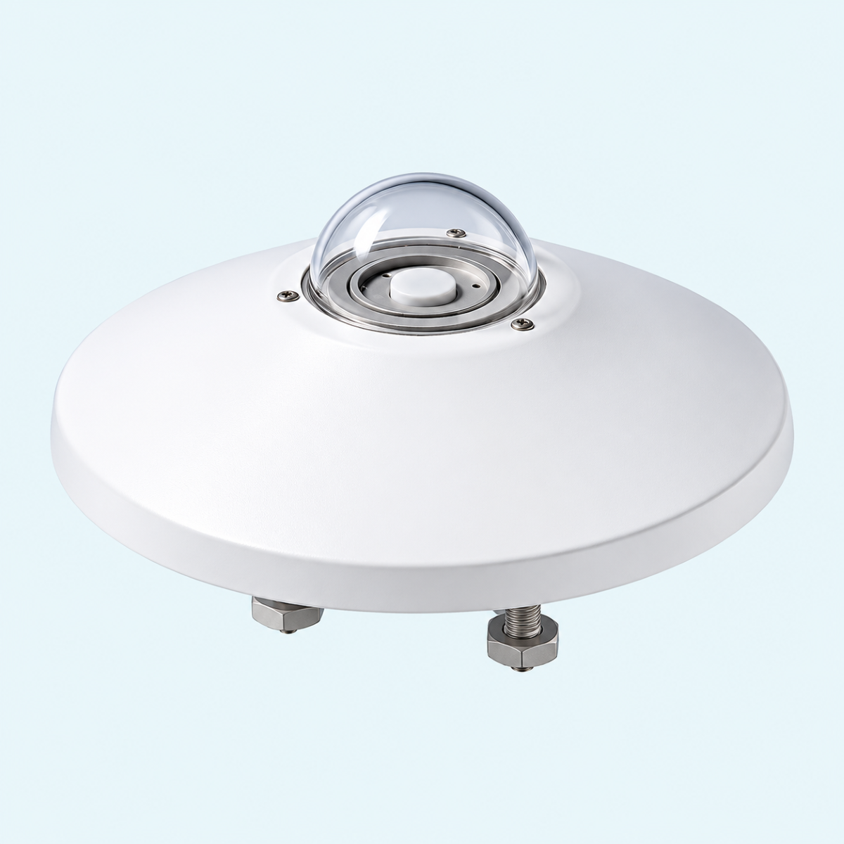
Each LPUVA03 probe is individually calibrated and equipped with a diffuser for cosine correction, a protective dome and an M12 connector. Depending on the selected version, it offers passive mV output without external power, normalized 4…20 mA or 0…10 Vdc output, or RS485 MODBUS-RTU communication. The probe operates within a temperature range of −20…+60 °C, with optional connection cables available in lengths of 2, 5 or 10 m.

Typical Applications

  • Outdoor UVA irradiance measurement and monitoring

  • UVA irradiance data acquisition through analog output signals

  • Integration into RS485 MODBUS-RTU monitoring networks

Key Features

  • UVA irradiance measurement in the 315…400 nm spectral region

  • Photodiode sensor insensitive to visible and infrared light

  • Peak spectral response at 365 nm

  • Typical sensitivity of 70…200 µV/(W/m²)

  • Measurement range of 0…200 W/m² for normalized and RS485 output versions

  • Passive mV, 4…20 mA, 0…10 Vdc or RS485 MODBUS-RTU output options

  • Diffuser for cosine correction and protective dome

  • Operating temperature range of −20…+60 °C

  • M12 male connector with optional 2, 5 or 10 m cables

  • Individually calibrated, with calibration factor marked on the housing for passive output versions

Benefits

  • Dedicated UVA photodiode supports outdoor irradiance monitoring

  • Individual calibration supports interpretation of each probe's output

  • Passive mV output eliminates the need for an external power supply

  • Analog and RS485 output options allow integration with different monitoring systems

  • Cosine correction diffuser and protective dome support outdoor measurements

  • Optional 2, 5 or 10 m connection cables offer installation flexibility

Specifications

UVA Measurement

Measured quantity

UVA irradiance

Measurement unit

W/m²

UVA spectral region

315…400 nm

Sensor type

Photodiode

Spectral sensitivity

Insensitive to visible and infrared light

Typical sensitivity

70…200 µV/(W/m²)

Spectral response range (1/2)

342…384 nm

Spectral response range (1/10)

330…393 nm

Spectral response range (1/100)

320…400 nm

Peak spectral response

365 nm

Calibration uncertainty

<6%

Cosine response (f₂)

<6%

Linearity (f₃)

<1%

Impedance (non-normalized version)

0.5…1.0 kΩ


Output

Passive output

Voltage signal, expressed in µV per µW/cm²

Normalized current output

4…20 mA

Current output scaling

4 mA = 0 W/m²; 20 mA = 200 W/m²

Normalized voltage output

0…10 Vdc

Voltage output scaling

0 V = 0 W/m²; 10 V = 200 W/m²

Optional voltage output

0…1 Vdc (upon request)

Digital output

RS485 MODBUS-RTU

RS485 measurement range

0…200 W/m²


Power Supply

Passive output

No external power supply required

4…20 mA

10…30 Vdc

0…10 Vdc

15…30 Vdc

0…1 Vdc (upon request)

15…30 Vdc

RS485 MODBUS-RTU

5…30 Vdc


Environmental and Mechanical

Operating temperature

−20…+60 °C

Cosine correction

Diffuser

Protective dome

K5 dome

Included component

Silica gel cartridge

Connector

M12 male, 4-pole or 8-pole depending on version

Calibration

Individually calibrated

Calibration factor

Marked on the probe housing for converting the passive output signal into irradiance


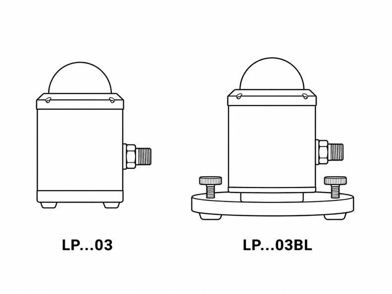
Model

LPUVA03

µV/(µW/cm²) output

LPUVA03BL

µV/(µW/cm²) output, base with levelling device

LPUVA03BLAC

Base with levelling device, 4…20 mA output

LPUVA03BLAV

Base with levelling device, 0…10 V output

LPUVA03BLS

Base with levelling device, RS485 MODBUS-RTU output


RS485 MODBUS-RTU Communication

Communication interface

RS485

Communication protocol

MODBUS-RTU

Sensor address range

1…247

Factory-preset address

1

Supported baud rates

9600, 19200, 38400, 57600, 115200 bps

Factory-preset baud rate

19200 bps

Supported transmission modes

8-N-1, 8-N-2, 8-E-1, 8-E-2, 8-O-1, 8-O-2

Factory-preset transmission mode

8-E-1

Factory-preset receiving mode

Respect protocol; wait 3.5 characters after transmission

MODBUS measurement reading

Function code 04h (Read Input Registers)

UVA measurement resolution

0.1 W/m² (register 2)

RS485 output isolation

Not isolated

MODBUS operating mode

Activated 10 seconds after power-on


MODBUS Register Register address (LPUVA03BLS version only)

Quantity

Data format

0

Internal temperature in °C × 10

16-bit integer

1

Internal temperature in °F × 10

16-bit integer

2

UVA irradiance in W/m² × 10

16-bit integer

3

Status register

16-bit integer

4

Average value of the last 4 measurements

16-bit integer

5

Signal generated by the sensor in µV

16-bit integer


Connection Cables and Accessories

Model

CPM12AA4.2

Cable with 4-pole M12 connector on one end and open wires on the other end, 2 m

CPM12AA4.5

Cable with 4-pole M12 connector on one end and open wires on the other end, 5 m

CPM12AA4.10

Cable with 4-pole M12 connector on one end and open wires on the other end, 10 m

CPM12-8D.2

Cable with 8-pole M12 connector on one end and open wires on the other end, 2 m

CPM12-8D.5

Cable with 8-pole M12 connector on one end and open wires on the other end, 5 m

CPM12-8D.10

Cable with 8-pole M12 connector on one end and open wires on the other end, 10 m

CP24

PC connecting cable with built-in RS485/USB converter, 8-pole M12 connector on the sensor side and Type-A USB connector on the PC side, for MODBUS parameter configuration

Drawing

LPUVA03 Radiometric Probe Drawing

Downloads

LPxx03 Family Datasheet DownloadLPxx03 Family Datasheet
Probes-LPxS Family User Manual DownloadProbes-LPxS Family User Manual
LPxx03 Family CE Declaration of Conformity DownloadLPxx03 Family CE Declaration of Conformity